This chapter covers
- Setting up a scene ready for rendering
- Exploring how to get the most out of lighting settings
- Understanding how cameras work in OpenUSD
- Achieving an end result by rendering images from your scene

Figure 1:The scene we will create to learn about lighting, cameras and rendering in OpenUSD. It contains three .usd objects, a figure and a base which together form a statue, and a backdrop.
We created some objects on our stages and referenced other objects to populate our scenes, but you may have noticed that they still look a little flat and unrealistic, even those that have well-made materials added. Further, you may have noticed as you move your viewpoint around the scene that certain angles work better to show off the model, enhancing its appearance and offering a clearer view of the most important details. These are both issues to consider before you reach the final step of rendering an image or animation from your creation and this requires some aesthetic choices.
The solution to the first problem is the addition of some thoughtfully chosen and well-placed lighting that can add depth and atmosphere to a scene, enhancing the fact that they’re three dimensional by highlighting the shape and form of your meshes. Done well, lighting can transform your scene from a lifeless sketch where everything feels a bit like plastic, into anything from a professional looking studio shot, an exterior scene bathed in dawn light, or even a fantastical movie still with magical glowing orbs floating around. If your scene looks dull or unnatural, lighting is your friend.
Once the scene is lit, it’s time to consider the second problem, the point of view (POV) of the viewer. It’s time to start playing the role of a photographer. Whether your aim is to render a 2D image from your scene or you are building a 3D environment that is intended to be rendered and experienced in real-time, such as a digital twin, a VR/AR application, or a game, then you will need to establish a viewpoint from which to capture the scene. This is achieved by placing a camera on the stage.
Astute decisions with your camera will go a long way towards achieving the look and feel you are aiming for. Do you want the scene to look like a crisp, clear diagram of an accurate engineering model, are you hoping to create a portrait with a strong focus on the subject and gently blurred background, or do you want your 3D models to loom towards the viewer with a highly exaggerated perspective? Much like lighting, the camera placement and choice of settings will have a profound effect on the quality, feel and impact of the final rendered image or the immersive experience.
Let’s explore the process of setting up and rendering an OpenUSD scene. Initially, we will use skills learned in earlier chapters, such as importing, creating and transforming prims to create a simple scene containing a statue and a background.
Next, we’ll move on to understanding lighting types and properties, where we’ll explore the nuances of different lighting techniques, including positioning, intensity, and color settings, to bring your scene to life with realistic and professional illumination.
Having lit our stage, we will then learn how to harness camera settings and provide guidance on configuring various camera parameters to achieve the desired framing and perspective for your scene.
Then finally, a section on rendering your stage will tie all of these elements together, demonstrating how to use Blender or USD Composer to produce high-quality visual outputs. By the end of this chapter, you will have a solid understanding of how to leverage Python scripts to control the most fundamental aspects of scene rendering with OpenUSD. Figure 1 shows a render from the scene we will be building.
You have an opportunity to build on the skills you learned earlier by setting up the scene using the code in the 5.1 Setting Up the Scene and referencing the objects we have provided.
5.1 Setting Up the Scene
Let’s start off this process by enhancing some of the techniques we learned in previous chapters. We’re going to create a new stage and populate it by importing some .usd objects, i.e, a figure.usd, base.usd, and a backdrop.usd. This can serve as a revision of skills learned in previous chapters whilst also setting up the scene for the rest of the chapter.
Before we begin, remember our discussion in Chapter 2 about the importance of considering the best location for the files and being mindful of your directory structures when choosing where to save files. We recommend using the following directory structure for the statue scene we’re about to create and ensuring that you have set /Ch05 as your working directory:
/Ch05
├── Assets
│   ├── textures
│   │   └── <All Texture Files>
│   ├── Backdrop.usd
│   ├── Base.usd
│   └── Figure.usd
└── statue.usd
Using the structure above will allow you to move the ‘Ch05’ folder anywhere without breaking the references contained in statue.usd, as all those references are contained within the root directory.
On the stage we are about to create, as it is unlikely that you would want to separate the figure from the base it is good practice to arrange the referenced figure.usd and base.usd so that they are children of one Xform, named ‘Statue’. That way if you ever need to move the statue to another position on the stage, you can do so by manipulating the parent Xform of the figure and the base, rather than the figure and base independently:
from pxr import Usd, Sdf, UsdGeom, Gf

stage = Usd.Stage.CreateNew("statue.usd")

# Define the ‘Statue’ Xform
statue = UsdGeom.Xform.Define(stage, '/World/Statue')

# Define 'Figure' under 'Statue' replace with your figure.usd path, example:  "./Assets/Figure.usd"
figure = UsdGeom.Xform.Define(stage, '/World/Statue/Figure')
figure_references: Usd.References = figure.GetPrim().GetReferences()
figure_references.AddReference(
	assetPath= <your file path to figure.usd ex: "./Assets/Figure.usd">
)

# Define 'Base' under 'Statue' replace with your base.usd path, example:  "./Assets/Base.usd"
base = UsdGeom.Xform.Define(stage, '/World/Statue/Base')
base_references: Usd.References = base.GetPrim().GetReferences()
base_references.AddReference(
	assetPath= <your file path to base.usd ex: "./Assets/Base.usd">
)

backdrop = UsdGeom.Xform.Define(stage, '/World/Backdrop')
backdrop_references: Usd.References = backdrop.GetPrim().GetReferences()
backdrop_references.AddReference(
	assetPath= <your file path to backdrop.usd ex: "./Assets/Backdrop.usd">
)

stage.Save()
After saving the stage, you should have a scene that contains a backdrop, and a statue, which consists of the figure and the base. However, depending on your chosen viewer, you may find that the stage is very dark, so let’s move on to adding some lighting.
5.2 Mastering Lighting
Lighting is a fundamental aspect of 3D scene creation, as it can dramatically influence the mood, depth, and realism of your environment. Let’s delve into the process of creating and positioning lights using OpenUSD programming. We’ll explore various basic lighting types and understand when and why to use different lighting methods. Additionally, we’ll first explain how to set light variables programmatically. Then we’ll show you how to improve your scene with realistic lighting by using HDR or .exr textures, which replicate environmental lighting and provide backgrounds for your images. By mastering these techniques, you’ll be able to craft visually compelling scenes that evoke the atmosphere or style that you are trying to create.
It is often useful to be able to turn lights on and off when building a 3D scene. For this reason, we’ll start this section with an introduction to hiding and showing prims. This is applicable to any prim on your stage but is often used to set the visibility of light prims.
5.2.1 Setting the Visibility of Prims
The following code listings will define custom functions that can be used to toggle the visibility of any prim on any stage. They will be used later in this section to hide some of the lights on our Statue stage. Remember that custom functions are not retained if the command terminal is closed or refreshed, so you may need to redefine these if you are unable to complete the code in this chapter in one session.
def hide_prim(stage: Usd.Stage, prim_path: str):
    """
	Hide a prim
	::params:
    	stage (Usd.Stage): The USD Stage
    	prim_path (string): The prim path of the prim to make invisible
    """
    # Get the prim at the prim path
    prim = stage.GetPrimAtPath(prim_path)
    # Get the prim's visibility attribute
    visibility_attribute = prim.GetAttribute("visibility")
    if visibility_attribute:
        visibility_attribute.Set("invisible") # Set the attribute value into "invisible"
Program 1:Make a Prim Invisible
To make a prim visible again, we can use the following code that defines a function, show_prim, which sets the prim’s visibility attribute to “inherited”, meaning it will follow the visibility state of its parent prim. This method is particularly helpful in complex hierarchical scenes, as it maintains consistency and simplifies scene management by reducing the need for multiple manual adjustments of individual prims. It can help to manage changes more efficiently, ensuring that updates propagate through the hierarchy without individual modifications.
def show_prim(stage: Usd.Stage, prim_path: str):
    """
    Show a prim
    ::params:
        stage (Usd.Stage): The USD Stage
        prim_path (string): The prim path of the prim to make visible
    """
    prim = stage.GetPrimAtPath(prim_path)
    visibility_attribute = prim.GetAttribute("visibility")
    if visibility_attribute:
        visibility_attribute.Set("inherited") # Set the attribute value into "inherited". If the parent prim is visible, the prim will be shown
Program 2:Make a Prim Visible
Later in this section we will use these techniques to make prims invisible and switch lights off on our stage. First, let’s start adding some lights to illuminate the statue.
5.2.2 Creating Lights
With your stage now set up and populated, it is time to beautify it with some carefully placed illumination. First, consider what type of lighting will be required to achieve the look and style you are aiming for. For example, if you are trying to create the feel of a professional studio shot, you might decide to use the three-point lighting system. (This is the look we’re going for in our Statue scene, so more on that in 5.2.3 Three-Point Lighting). If, on the other hand, you are trying to recreate the feel of flash photography, you may only need a single, bright, directional light positioned very close to the camera to simulate a camera mounted flash. Perhaps instead, you are trying to create a natural outdoor feel in your scene, in which case you will want the feel of distant light coming from one direction, like a midday sun, mixed with more diffuse light coming from all other parts of the sky. In this latter case, you would utilize OpenUSD’s Distant or Dome lights.
Here is a brief summary of each of the six types of light that are available in OpenUSD.
- Rect Light: Emits light from a rectangular area, creating broad and soft lighting. Perfect for simulating large light sources such as windows, softboxes, or other panel lights.
- Disk Light: Emits light from a circular disk area, providing softer and more diffused illumination compared to a point light. Ideal for simulating area lights like LED panels or ring lights.
- Sphere Light: Emits light from a spherical area. It can be configured to behave like a point light, emitting light uniformly in all directions from a single point, so is often used to simulate an incandescent bulb. -Cylinder Light: Emits light in a cylindrical shape, often used to simulate tube lights or elongated light sources.
- Distant Light: Represents light coming from a specific direction, simulating sunlight or other distant light sources. It uniformly affects all objects, regardless of their position.
- Dome Light: Encompasses the entire scene with light, simulating the effect of a sky or environmental lighting. Often uses HDR images as texture to provide realistic and ambient lighting, and background scenery.
Figure 2 shows the four types of ‘area’ light that have a physical presence on the stage, a specified size, and can be moved around to alter their effect on the scene. The two additional types of light, the distant and dome lights, do not occupy a space on the stage, but cast light onto it from a distance. These latter two can only be rotated to alter the angle of light on the stage.
Figure 2:OpenUSD Light Types: Cylinder (3D, tubular), Disk (2D, circular), Rectangle (2D, area illumination), and Sphere (3D spherical, radiant light).
Next, we’ll create one of each type of light on our stage. As we do so, we’ll explore some universal APIs that apply to any type of light on your stage, then examine each type of light individually to understand the APIs that are specific to that type, for example, the cylinder light has both a radius and length setting, whereas a disc light has only a radius setting as it is a flat, 2D source of light.
To add lights into the stage, first we need to load the UsdLux package, which provides a representation for lights and related components. We’ll also import the Gf module to enable vectors for modifying the light’s transforms and other properties:
from pxr import UsdLux, GfLet’s define an Xfrom prim named ‘Lights’, which will serve as the parent prim for all the lights we will add later, then add one rectangular light source:
rect_light = UsdLux.RectLight.Define(stage, "/World/Lights/RectLight") Next we’ll move the Rect light away from its default position at the World Origin to a position right and front of the statue, then rotate it by 45 degrees on the y axis. To do this, you can use the AddTranslateOp and AddRotateXYZOp APIs to modify the light’s location, and rotate the light around its X, Y, and Z axes:
rect_light.AddTranslateOp().Set(Gf.Vec3d(100, 100, 200))
rect_light.AddRotateXYZOp().Set(Gf.Vec3d(0, 45, 0))
Remember, if you decide you want to move the light again, you do it by modifying the existing translate op with the translate_op.Set() method, or clear it completely with ClearXformOpOrder().
As important as a light’s location is the intensity of its illumination and the color of light it gives off. These properties are set using the CreateIntensityAttr() and the CreateColorAttr(), respectively. These two APIs are commonly used together to define the overall appearance of a light source in OpenUSD. Let’s apply them to our Rect light:
CreateIntensityAttr: This API is used to set the intensity or brightness of a light source. It creates an intensity attribute for the light, which can be specified as a scalar value (e.g., a float).
rect_light.CreateIntensityAttr(30000)CreateColorAttr: This API is used to set the color of a light source. It creates a color attribute for the light, which can be specified as a RGB value. Here we will set the color to white by using the values (1, 1, 1):
rect_light.CreateColorAttr(Gf.Vec3f(1, 1, 1)) # RGB (1, 1, 1) defines a white colorYou can use the above commands to affect the Rect light’s hue, saturation, and brightness on the stage.
The above APIs are applicable for all lights. However, some of the APIs are only applicable for a certain type of lights, so next we’ll look more specifically at each type of light. As we go through them, we’ll add each one to the stage and manipulate their transforms and properties, so that you can observe their effects.
Remember, if you are using Blender and you want to view the lights as you add them, you will need to run a stage.Save() command, reimport the .usd file in its new state, and change the viewport shading to Render mode.
The following four light types will translate properly from USD into Blender.
Rect Light
The Rect light is a 2D flat plane that offers a wide source of light from one of its surfaces, giving soft, natural shadowing. They are suitable for areas that require uniform, wide light distribution, such as under cabinet lighting or to replicate windows or a photographer’s soft box diffuser. You can define the height and width to specify its size.
We’ve already created, translated, and set the Rect lights intensity and color using the APIs that are applicable to all light types. Now let’s set the APIs that are specific to a Rect light, its Height and Width:
rect_light.CreateHeightAttr(100)
rect_light.CreateWidthAttr(100)
Figure 3 shows the Rect light we have just created on the Statue stage. Here the Rect Light is being used as a broad illuminator of the subject. Positioned at the front and right of the subject, angled at 45° towards it, and being large causes the light to illuminate most of the front surfaces and cast very soft shadows.
Figure 3:The Rect light on the stage, as viewed in USD Composer. Being positioned 45° in front of the subject allows this light to reach most of the front surfaces. As it is large the shadows created are very soft.
Disk Light
Like the Rect light, the Disk light provide a wide, even source of light, making it ideal for illuminating large areas or workspaces, and their 2D form makes them easy to position close to other objects, for example, you might place one at the end of a flashlight model or up against a ceiling to represent a recessed LED light. They only emit light from one surface and as a disc light is 2D, you can only set its radius. Let’s add on to the stage:
disk_light = UsdLux.DiskLight.Define(stage, "/World/Lights/DiskLight")
disk_light.CreateRadiusAttr(50)
You can add translate, rotation, color, and intensity to the light as usual:
disk_light.AddTranslateOp().Set(Gf.Vec3d(0, 200, 0))
disk_light.AddRotateXYZOp().Set(Gf.Vec3d(-90, 0.0, 0))

disk_light.CreateColorAttr(Gf.Vec3f(1, 1, 1))
disk_light.CreateIntensityAttr(30000)
Figure 4 shows the Disc light we have just created on the Statue stage. Positioned directly above the subject and having a radius wider than the statue, this Disc light is highlighting the upper surfaces of the statue and revealing slightly more of its form than the Cylinder light. Having a radius larger than the subject causes it to cast soft shadows.
Figure 4:The Disc light on the stage, as viewed in USD Composer. Positioned above the subject, and being wider than it, this light highlights the upper surfaces and casts soft shadows.
Sphere Light
As the name suggests, a sphere light is spherical in shape, distributing light evenly in all directions. A sphere light emits light in all directions, most closely resembling a bulb or other omnidirectional light source. You can specify the radius of the sphere.
sphere_light = UsdLux.SphereLight.Define(stage, "/World/Lights/SphereLight")

sphere_light.CreateRadiusAttr(5.0)

sphere_light.AddTranslateOp().Set(Gf.Vec3d(-22, 166, 66))

sphere_light.CreateColorAttr(Gf.Vec3f(1, 1, 1))
sphere_light.CreateIntensityAttr(400000)
While a sphere light emits light in all directions, it can be approximated as a point light source for many practical purposes, especially when the sphere’s diameter is much smaller than the objects being illuminated or it is far away. Treating it as a point light helps simplify calculations, easing the burden on renderers, and making it more suitable for hardware-constrained environments, such as mobile devices or virtual reality systems. To turn you sphere light into a point light:
sphere_light.CreateTreatAsPointAttr(True)In its current form this light will not import well into Blender. This is due to the way Blender calculates the intensity of a point source light, which results in a much lower intensity. If you are using Blender as your viewer, then you should return the sphere to its full 3D state with:
sphere_light.CreateTreatAsPointAttr(False)Figure 5 shows the Sphere light we have just created on the Statue stage. Being relatively small and positioned close to the statue’s head and shoulder, this light is used here to accentuate those areas of the subject. Also, it provides point highlights on many other areas, which is a useful way to accentuate the reflectivity of a material. The larger the radius of the sphere, the softer its shadows will become, with a point light source giving very hard shadows.
Figure 5:The Sphere light on the stage, as viewed in USD Composer. Here the light is small and placed close to the area we want to accentuate. It also provides many small point highlights that accentuate the reflectivity of the statue’s material.
Distant Light
The Distant light (called a ‘Sun’ light in Blender) is a highly directional light, replicating light emitted from a very distant source. Consequently, the rays are considered to be parallel to each other, and will give relatively hard shadows. It is ideal for mimicking the light from the sun or moon, or could be used to represent a floodlight that is a long way from the subject. You can change the angle of the distant light by adjusting its rotation.
distant_light = UsdLux.DistantLight.Define(stage, "/World/Lights/DistantLight")
# Set rotation
distant_light.AddRotateXYZOp().Set(Gf.Vec3d(-17, -30, -50))
distant_light.CreateIntensityAttr(1.0)Figure 6 shows the Distant light we have just created on the Statue stage. Here the light is approximating overhead sunlight, so the light is uniform across the whole of the subject, except where it is shadowing itself, and the shadows are relatively hard. Notice how it floods the whole scene, so that even the backdrop is affected.
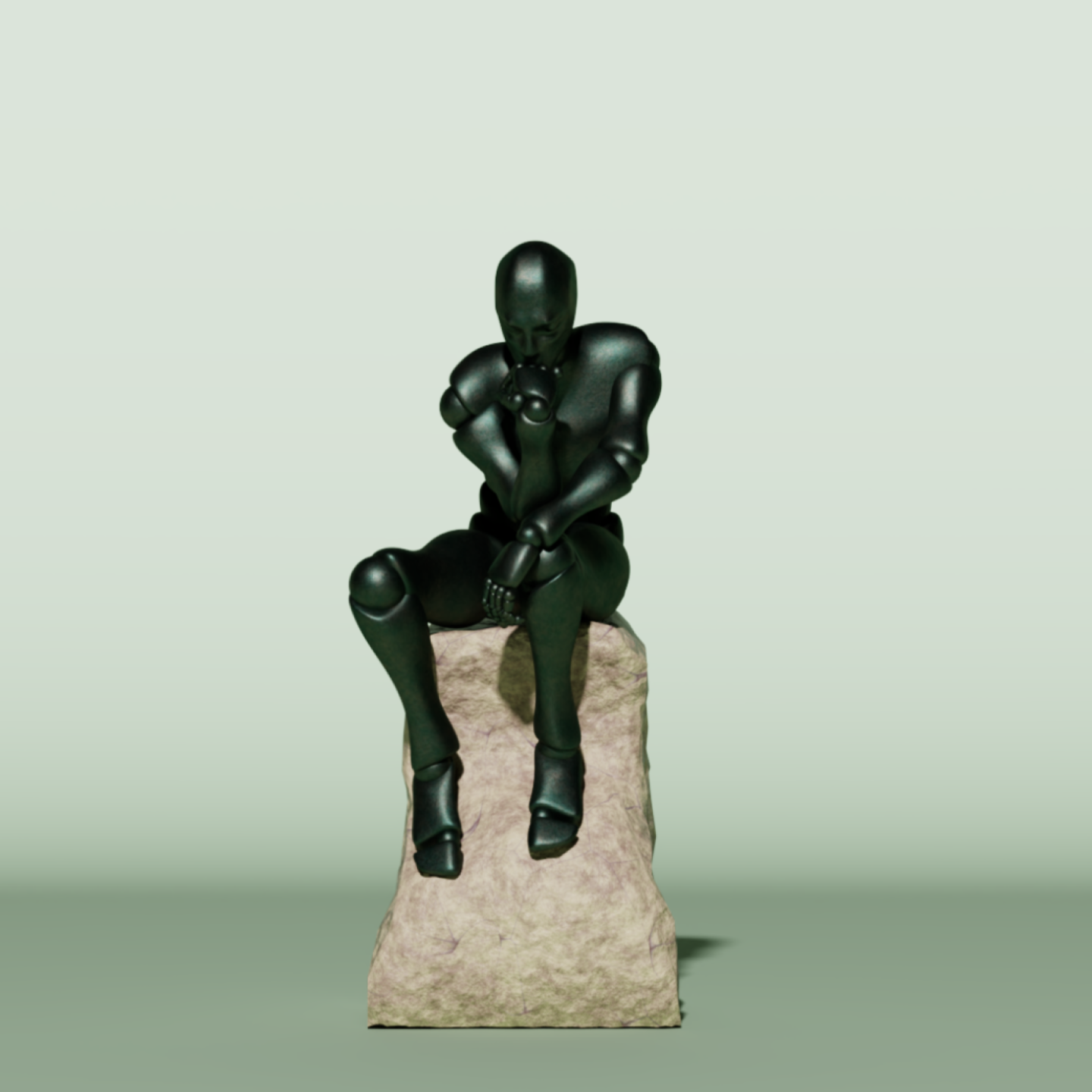
Figure 6:The Distant light on the stage, as viewed in USD Composer. Replicating overhead sunlight coming from an angle above and slightly in front of the statue, this Distant light is lighting all areas of the statue and the backdrop.
Cylinder Light
Cylinder lights most resemble a fluorescent tube, which makes them perfect for task lighting or highlighting specific areas in a scene, and their long, slim design allows them to fit into narrow spaces. Let’s define, translate, and set the intensity and color of a cylinder light:
cylinder_light = UsdLux.CylinderLight.Define(stage, "/World/Lights/CylinderLight")

cylinder_light.AddTranslateOp().Set(Gf.Vec3d(-100, 100.0, 0))
cylinder_light.AddRotateXYZOp().Set(Gf.Vec3d(0, 0.0, 90))

cylinder_light.CreateIntensityAttr(100000)
cylinder_light.CreateColorAttr(Gf.Vec3f(1, 1, 1))
APIs specific to Cylinder lights allow us to define the length or the radius of the cylinder:

# Change the height/length of the cylinder
cylinder_light.CreateLengthAttr(100.0)
# Change the radius of the cylinder
cylinder_light.CreateRadiusAttr(5.0)
Figure 7 shows the Cylinder light we have just created on the Statue stage in USD Composer. Notice how the shadows cast by this light are quite hard. This is because the light has a relatively narrow radius making it a thin strip of light. If you increase the radius of a Cylinder light, the shadows it casts will become softer. Also notice how both its length, almost the same as the figure, and its location beside the statue allow it to create a rim of light along the entire side of the subject giving it definition by separating it from the background. As a Cylinder light does not emit light from either end, you will notice the small dark circle on the floor that the end is pointed towards.
Figure 7:The Cylinder light on the stage, as viewed in USD Composer. Here it is being used to create a rim of light along the side of the statue, effectively separating it from the background.
Dome Light
Dome Lights emit directional light inward from a sphere that surrounds the entire scene. They are used to replicate ambient lighting conditions consistent with a distant external environment, such as a sky or from the internal lighting of a building or room, such as a large warehouse or studio space. They differ from Distant lights as they emit inwards from all angles, not just one
Dome lights are especially effective when paired with High Dynamic Range Images (HDRI) which can be used as textures to simulate realistic lighting environments. These are usually stored as .hdr or .exr files, as these can accommodate the high color depth and a wide dynamic range required to provide realistic lighting.
Similar to the way diffuse or emissive image textures can be added to materials, image textures can also be applied to a dome light in order to create detail that will vary the intensity and color of light in different areas of the sphere, and also provide a background image to a scene. When viewed in 2D, images used for environmental dome lighting appear distorted, but when applied to a sphere, they provide a seamless 360 degree background for a 3D scene, and illumination consistent with the image. For example, if the texture image applied to a Dome light shows a setting sun, the light it emits will be low angled and orange in color, with strong directional light coming from the position of the sun, and less ambient light coming from the rest of the sky.
Let’s add one to the scene. Conventionally, Dome lights (and sometimes Distant lights) are considered part of the environment of the scene, therefore, they get placed under an ‘Environment’ prim. We’ll name the Dome light prim ‘Sky’. (Notice that we’ll also rotate it by -90 degrees on the x axis. This is because we’re going to add a landscape texture to it shortly, and this rotation will make the landscape horizontal):
dome_light = UsdLux.DomeLight.Define(stage, "/Environment/Sky")
# rotate the dome
dome_light.AddRotateXYZOp().Set(Gf.Vec3d(-90, 0, 0))
You can also change the color and intensity:
dome_light.CreateIntensityAttr(3000)
dome_light.CreateColorAttr(Gf.Vec3f(0.5, 0.75, 1.0))
Figure 8 shows the Dome light we have just created on the Statue stage. Currently, the Dome light is emitting a uniform, blue colored light from all directions of the sky sphere resulting in a flat, but natural looking light with very soft shadows and blue caste over everything. The caste is present because we set the Light’s color to a sky blue.
Figure 8:The Dome light on the stage, as viewed in USD Composer.
This type of uniform, all-encompassing light may be useful in some circumstances, perhaps if you were replicating the light from a very overcast sky, or if you were only interested in creating a very crisp, clean stage to clearly view something like an engineering model. However, it is more common for the Dome light to be used as both a light source and a background by applying a texture image to it. The assets you downloaded at the start of this chapter contain a basic .exr file named ‘Landscape’ that you can use for this purpose. It is located in “./Assets/textures”.
Here is how we utilize .hdr or .exr image files to assign image textures to the dome lighting:
dome_light.CreateTextureFileAttr().Set("<your/path/to/hdr/or/exr/file ex: './Assets/textures/Landscape.exr'>") Currently, the backdrop is filling the background of the scene and preventing us from seeing the image texture that we’ve just applied to the Dome light. Now, let’s apply the code we learned in Program 1 to make the backdrop invisible, so that we can see the image texture on the Dome light in the background:
hide_prim(stage, "/World/Backdrop")
stage.Save()
Figure 9 shows the Dome light we have just created on the Statue stage, with a HDRI texture applied and the backdrop made invisible so that you can see the texture image as a background. The detail and colors in the image file will be reflected in the direction and color of the light that is thrown onto your scene, resulting in a highly natural appearance.
Figure 9:The Dome light with a HDRI texture added and the backdrop removed, as viewed in USD Composer. Details and colors within the image texture will be used to calculate the lighting of the scene, providing a very realistic and natural look.
Having filled our Statue scene with every type of light, let’s be a bit more selective and use the hide_prim function to remove some lights, then we’ll add a new light to leave us with a nice three-point lighting set up.
5.2.3 Three-Point Lighting
When viewing each of the lights individually above, you may have noticed that each one on its own is not really sufficient to fully light the subject, with the possible exception of the Distant and Dome lights. Usually, a scene will benefit from combining two or more light sources, so let’s examine a commonly used technique in studio lighting. The three-point lighting system is used to light a subject in a pleasing way, without too many areas of deep shadow, whilst allowing it to stand out against a background. It involves the use of a key light, fill light, and back light.
- Key light is the primary light source and is used to illuminate the subject, creating strong shadows and highlights. It is usually the brightest light of the three.
- Fill light is positioned opposite the key light to soften the shadows and reduce contrast.
- Back light is placed behind the subject to create a rim of light that separates the subject from the background, adding depth to the scene.
Figure 10 shows a diagram of how a typical three point lighting setup might look. Note that the lighting position is decided in relation to the camera’s position, with choices being made on whether the dominant light is coming from the left or right and how that might be balanced with lighting placed on the opposite side of the camera. Further, the position of a Back Light must consider the camera position by being somewhere opposite it, as its role is to throw a rim of light around the edges of the subject. The number of arrows extending from each light indicates the relative levels of illumination they might provide in a standard setup. As with any lighting setup, this is a subjective choice of position and amount of illumination that will vary depending on the desired effect.
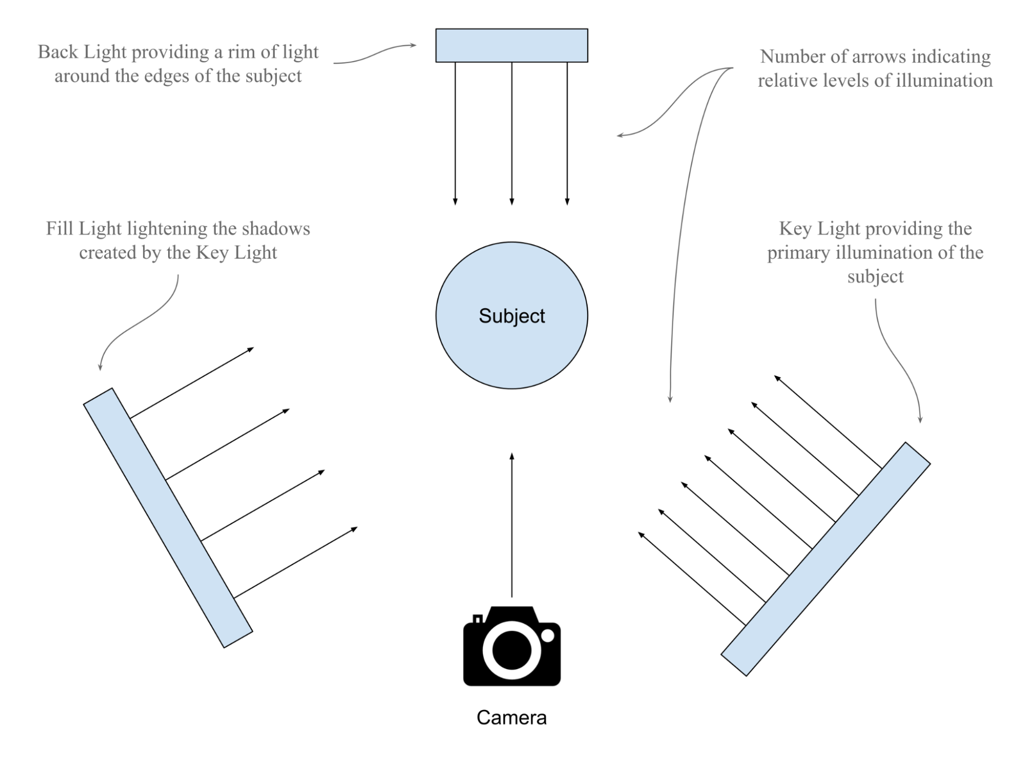
Figure 10:A diagram showing the basic principles of the three point lighting setup. The choice of lighting angles are made in relation to the viewing position of the camera. Viewed from this camera position, the Key Light would provide strong light from the right, with lower light from the Fill Light on the left to reduce the density of shadows thrown by the Key Light. Also, the Back Light would create a rim a light around the edges of the subject, which isolates it from any background.
Let’s start by making four of the lights we created above invisible. By making the cylinder, sphere, distant and dome lights invisible on our Statue scene, we will be left with the rectangle light working as a Key Light and the disc light working as a Back Light. As we have already defined the function hide_prim` when we made the backdrop invisible, we can simply apply that function to the four lights we want to make invisible:
hide_prim(stage, "/World/Lights/CylinderLight")
hide_prim(stage, "/World/Lights/SphereLight")
hide_prim(stage, "/World/Lights/DistantLight")
hide_prim(stage, "/Environment/Sky")
Next, let’s add a new light that can act as a Fill Light to balance out the Key Light. We’ll use another Rectangle Light and call it ‘FillLight’. Then we’ll want to position it the the left of the subject, opposite the Key Light and set it’s intensity to half that of the Key Light:
fill_light = UsdLux.RectLight.Define(stage, "/World/Lights/FillLight")
fill_light.CreateHeightAttr(100)
fill_light.CreateWidthAttr(100)

fill_light.AddTranslateOp().Set(Gf.Vec3d(-180, 100, 200))
fill_light.AddRotateXYZOp().Set(Gf.Vec3d(0, -45, 0))

fill_light.CreateColorAttr(Gf.Vec3f(1, 1, 1))
fill_light.CreateIntensityAttr(15000)
As we previously made the backdrop invisible, you may now wish to restore its visibility by applying the code we learned in Program 2 which defines the function ‘show_prim’ returning a prim’s visibility by making it inherit the visibility of its parent prim. Then remember to save the stage so that the changes can be viewed:
show_prim(stage, "/World/Backdrop")
stage.Save()
Figure 11 shows the stage with a variation on the three point lighting system that will be left after the Sphere, Distant, and Dome lights have been made invisible. Here the Rect light is acting as the Key light providing the primary illumination; the Cylinder light is on the opposite side of the subject to lighten the shadows created by the Key light; and the Disc light, even though it is not behind the subject, is taking the role of a Back light by creating a rim of light around the upper part of the statue.
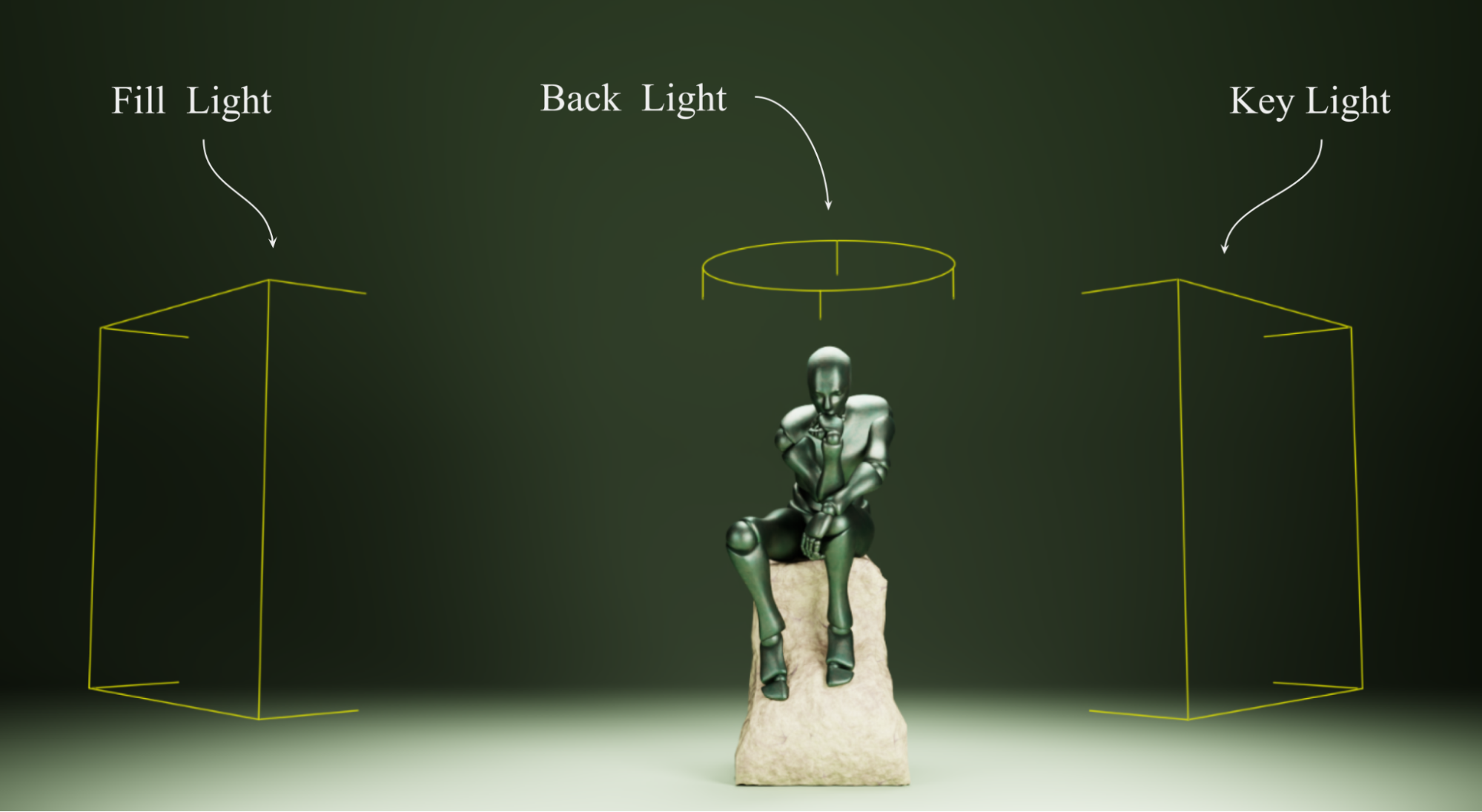
Figure 11:The Statue stage with a variation on the 3 Point lighting system, showing the first Rect light we created as a Key light, the second Rect Light we created as a Fill Light and the Disc light as a Back light.
If you want to play around with combinations of the various lights on the stage, then the same approach we used to make the backdrop visible can be used to restore the visibility of any lights you have on the stage. The show_prim function has already been defined, so you only need to call it for the prim you want to make visible again. Remember, each time you make a change you must save the stage and reload or re import the .usd file in its new state to your viewer.
Now that we’re satisfied with how we’ve lit our scene, let’s go on to introduce a camera and learn how to work with important camera settings that will determine the style and composition of your final image.
5.3 Harnessing Camera Settings
A fundamental requirement for computer-generated imagery is that there is a viewport into the image, often referred to as the camera. In USD, the camera serves as the virtual lens through which the scene is viewed and rendered. Creating and configuring this camera correctly is crucial for achieving the desired visual output.
5.3.1 Creating a Camera
Let’s examine how to set up a perspective camera using OpenUSD programming. In the following example, we’ll start by importing the necessary modules from the pxr library then opening a USD stage.
from pxr import Usd, Sdf, UsdGeom You can define the camera on the stage using UsdGeom.Camera, specifying the path for the camera.
stage = Usd.Stage.Open("statue.usd")
# Define camera prim path
camera_path = Sdf.Path("/World/Cameras/Cam1_Standard_Front")
# Create a camera at the defined path
camera: UsdGeom.Camera = UsdGeom.Camera.Define(stage, camera_path)
It is highly unlikely that the camera’s default location will produce the shot you are hoping for, so let’s progress on to moving and rotating the camera to set up your shot.
5.3.2 Setting up Camera Translate and Rotation
Having placed a camera in the statue scene, you’ll notice that its position defaults to the point at the very center of the scene where x, y, and z values are zero, known as the ‘World Origin’. In addition, its direction will default to using the y axis as upwards and it will point along the z axis (see Figure 12).

Figure 12:Default Camera Position in OpenUSD. By default, a camera uses the y-axis as the up axis and looks in the -z direction.
Let’s begin to move our camera around the stage, to line up our shot of the statue.
camera.AddTranslateOp().Set(value=(0, 100, 1000))
stage.Save()
Notice that the camera’s xyz coordinates are (0, 100, 1000), and the statue is near the position (0, 0, 0) and 160 in height. Therefore, the camera is just above the middle of the statue, pointing at it from 1000 scene units away in the -z direction.
5.3.3 Understanding Camera Attributes
In OpenUSD, many camera settings work in an identical way to a physical camera. The terms focal length, aperture, and focus distance relate to characteristics and settings of physical lenses. Any readers already familiar with photography will be aware of how these three lens settings impact the camera’s view. Whether your camera is capturing static images of your scene, moving around following the action in an animation, or capturing the point of view (POV) of a player in a game, you will need to consider these three important settings. All are crucial for setting up a shot to achieve the desired effect.
In addition to these three settings, two other attributes that do not replicate physical cameras, but are common in 3D applications include the projection type and the clipping range. Let’s explore each of these settings.
Focal Length
The focal length of a camera lens determines its field of view, i.e, how zoomed in or out the shot is. A short focal length (like 18mm) captures a wide view, showing more of the scene, and is referred to as Wide Angle. A long focal length (like 100mm) zooms in on a smaller part of the scene, making distant objects appear closer and is referred to as Telephoto. In photography, a 50mm lens is commonly referred to as a standard lens, as it most closely replicates the field of view produced by the human eye, which gives images a very natural feeling perspective. When a camera is created in OpenUSD, it will default to a focal length of 50mm.
The choice of focal length in a shot can have a dramatic impact on the resulting feel of an image. Wide angle shots have an exaggerated perspective that can be used to make an object loom into the viewer if it is close to the camera, or if the object is far away from the camera, it can appear dwarfed by its surroundings. Conversely, a telephoto shot will compress the perspective, meaning the object and its background all appear to be on the same plane giving a flattened feel to the shot.
To create the focal length attribute of the camera and set it we can use:
camera.CreateFocalLengthAttr().Set(50)Often, you will need multiple cameras in an OpenUSD stage to capture different perspectives and angles of the scene, providing a comprehensive view for analysis or presentation. Additionally, multiple cameras can simulate various viewpoints for complex visual effects or interactive experiences.
To help us explore focal lengths, let’s add another camera and set its position closer to the statue, lower and angled upwards, with a wide angle lens:
camera2_path = "/World/Cameras/Cam2_Wide_Angle_Low"
camera2 = UsdGeom.Camera.Define(stage, camera2_path)
camera2.AddTranslateOp().Set(value=(-115, 20, 130))
camera2.AddRotateXYZOp().Set(Gf.Vec3d((14, -50, 15)))

new_focal_length = 8.0
camera2.GetFocalLengthAttr().Set(new_focal_length)
Notice how the camera is now much closer to the statue but is still able to view the whole of it, as the focal length gives a considerably wider field of view when set at 8mm. Also notice how the angle of the shot and the distortion caused by the wide angle lens give a completely different feel to the image, distorting the statue and making it loom over the viewer with an exaggerated perspective (see Figure 13).
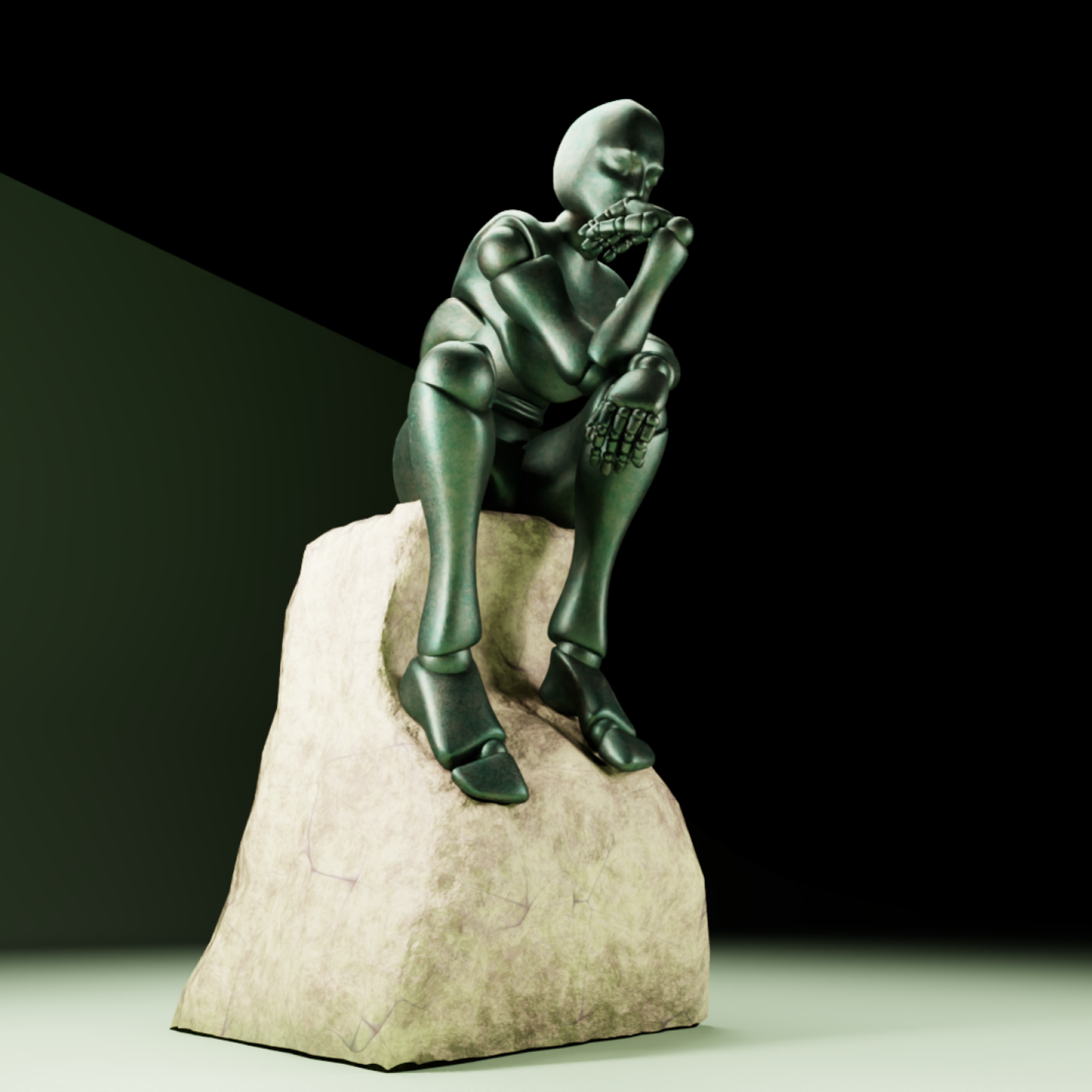
Figure 13:Illustrating the different feel that a wide angle lens can give an image. Although the camera is much closer to the subject, the field of view is much wider, causing the statue to become distorted and loom above the viewer.
Aperture, Depth of Field and fStop
In a physical camera, the aperture is the opening in the lens that controls how much light is allowed to pass through the open shutter, playing a key role in controlling the exposure of the shot. However, in most 3D platforms, exposure is usually dealt with by the renderer, so the aperture setting in OpenUSD does not influence the final exposure.
Another very important function of the aperture in a physical camera is its effect on the range of focus, or Depth of Field (DOF) in a shot. It is for this ability to control the DOF that the aperture setting is most commonly used in 3D software.
The DOF determines the distance from the camera that objects come into, and go out of focus. It can be a narrow range, perhaps everything between 10 and 11 meters from the camera being in focus, or it can be a very deep range with everything from 1 meter from the camera to infinity being in focus. Creative manipulation of the DOF can be very useful in adding realism to an image, as well as providing an artistic method of directing attention in a scene, by blurring out less relevant details and maintaining sharp focus on the object of interest.
A wide aperture, or low fStop value (like f/2.8) creates a shallow depth of field, usually used to draw attention to an object whilst keeping anything in the foreground and background blurry. A narrow aperture, or high fStop value (like f/16) increases the depth of field, bringing more of the scene into focus. This is useful if you have a scene with multiple differently spaced objects that need to be in focus, or for looking along the length of a long object that extends away from the camera, all the while keeping the background in focus too. In reality, OpenUSD replicates the effects of a physical camera’s aperture with multiple variables. It influences the DOF, and the amount of blurring outside of the DOF, by calculating ratios between the focal length, focus distance and the fStop settings. In practice however, specific control of the DOF is most easily accessed using just the fStop parameter in a camera’s properties.
In OpenUSD, the fStop value defaults to 0.0 when a camera is created. Setting the fStop to 0.0 creates an infinite DOF, meaning everything in the scene will be in sharp focus irrespective of its distance from the camera. This effect is helpful whilst arranging a shot, or when a scene is designed for examination of something like a digital twin. It is also commonly used in POV gaming where the player needs to be able to see everything in their field of view clearly. However, it would look very unnatural in a final rendered image that was aiming to replicate photographic or filmic qualities, as real cameras or our eyes are not capable of viewing the world that way. Physical cameras with extremely small apertures and wide angle lenses can achieve a deep DOF, but even then, they are not capable of keeping very close objects and a distant background in focus at the same time.
The fStop variable can be set as follows, where the value ‘2.0’ represents f/2. This will change the fStop on the first camera we put in the scene, as the code does not specify ‘camera2’:
camera.CreateFStopAttr().Set(2.0) As the fStop works in close conjunction with the Focus Distance to produce DOF effects, we will explore that next. Also, we will make additional changes to the fStop that will reveal how DOF can be used to bring subjects in and out of focus.
Focus Distance
Sometimes when scene building, if you have moved a camera, altered its focal length and/or fStop, you will notice that the subject has gone out of focus. If so, then you will need to adjust the setting that tells the camera how far away it should be focussing. In OpenUSD this is controlled by the focusDistance attribute on the UsdGeom.Camera object.
The focusDistance defaults to 0.0 when the camera is created. This has the same effect of negating any DOF as the default 0.0 fStop setting has; it makes everything in the scene be in focus no matter how far from the camera it is. If you want to take advantage of DOF effects, you will need to alter the focus distance accordingly.
Let’s deliberately set the focus distance to an incorrect value, so you can see the effect. Remember, the first camera we added to the scene was placed 1000 scene units away from the statue. Currently, its fStop has been set to 2.0 and the focus distance will have defaulted to 0.0. Therefore, despite the low fStop value which would normally provide a narrow DOF, the default focus distance of 0.0 means that the DOF is being ignored and the statue will remain in focus. However, if we set the camera’s focus distance to 500 scene units, then the narrow DOF effect will come into play and the statue will go out of focus:
new_focus_distance = 500
camera.GetFocusDistanceAttr().Set(new_focus_distance)
This loss of focus on the subject happens because the statue is 1000 scene units away from the camera but the camera is now focusing 500 units away from itself, and the fStop value of 2.0 that we set earlier does not give sufficient DOF to keep the statue in focus.
Let’s change the fStop again to see what happens with a higher fStop value:
new_fStop = 16.0
camera.GetFStopAttr().Set(new_fStop)
Increasing the fStop value to 16 will create a deeper DOF which will be sufficient to encompass the statue. In other words, even though the camera is still focusing on a point 500 scene units away, the DOF will extend beyond 1000 units away because the higher fStop delivers a deeper DOF.
Figure 14 compares the camera view with a narrow and a deep DOF. The left image shows how setting both a low fStop value (narrow DOF) and a Focus distance that is 500 scene units short of the subject has caused the DOF effect to make the statue out of focus. The right image shows how only increasing the fStop value (deepening the DOF) can bring the statue back into focus, even though the focus distance remains 500 scene units short of the subject.
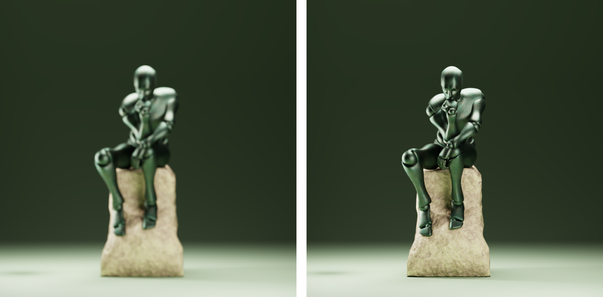
Figure 14:A comparison of a narrow depth of field with a deep depth of field. Even though the focus distance remained unchanged at 500 scene units short of the subject, the increased DOF provided by the higher fStop value is sufficient to bring the statue into focus.
If you ever intend to produce images from your 3D scenes that have a realistic sense of depth, you will want to explore this relationship between fStop and Focus Distance. Selectively and deliberately bringing elements in or out of focus can subtly direct the viewer’s attention to the important details, or turn a distracting backdrop into soft tones. Good use of the settings that control DOF can make or break an image.
Projection Type
Orthographic and perspective are two types of projections used in computer graphics that can be used to display models in different ways. Under orthographic projection, objects appear at the same scale regardless of distance, and parallel lines remain parallel. Orthographic views are often used in engineering to accurately represent a model as precise measurement and scale are often critical. Under perspective projection, objects appear smaller in the distance and parallel lines skew toward vanishing points. This view simulates how the human eye, and cameras see the world. Figure 15 demonstrates the different appearance of three cubes in a line, shown under orthographic and perspective projection. In OpenUSD a camera defaults to the perspective projection type when it is created.
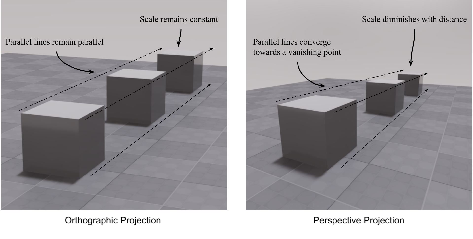
Figure 15:Comparison between orthographic projection and perspective projection. Perspective views are more natural and realistic, while orthographic views are more technical and provide a blueprint-like layout.
Clipping Range
The clipping range in OpenUSD refers to the distance limits within which objects are rendered by a camera. It is defined by two values: the near clipping plane and the far clipping plane. The near clipping plane is the closest distance at which objects are rendered, and the far clipping plane is the furthest distance at which objects are still visible. Any object in the scene that is outside of the clipping plane range will not appear in the render.Figure 16 provides a diagram of clipping planes.
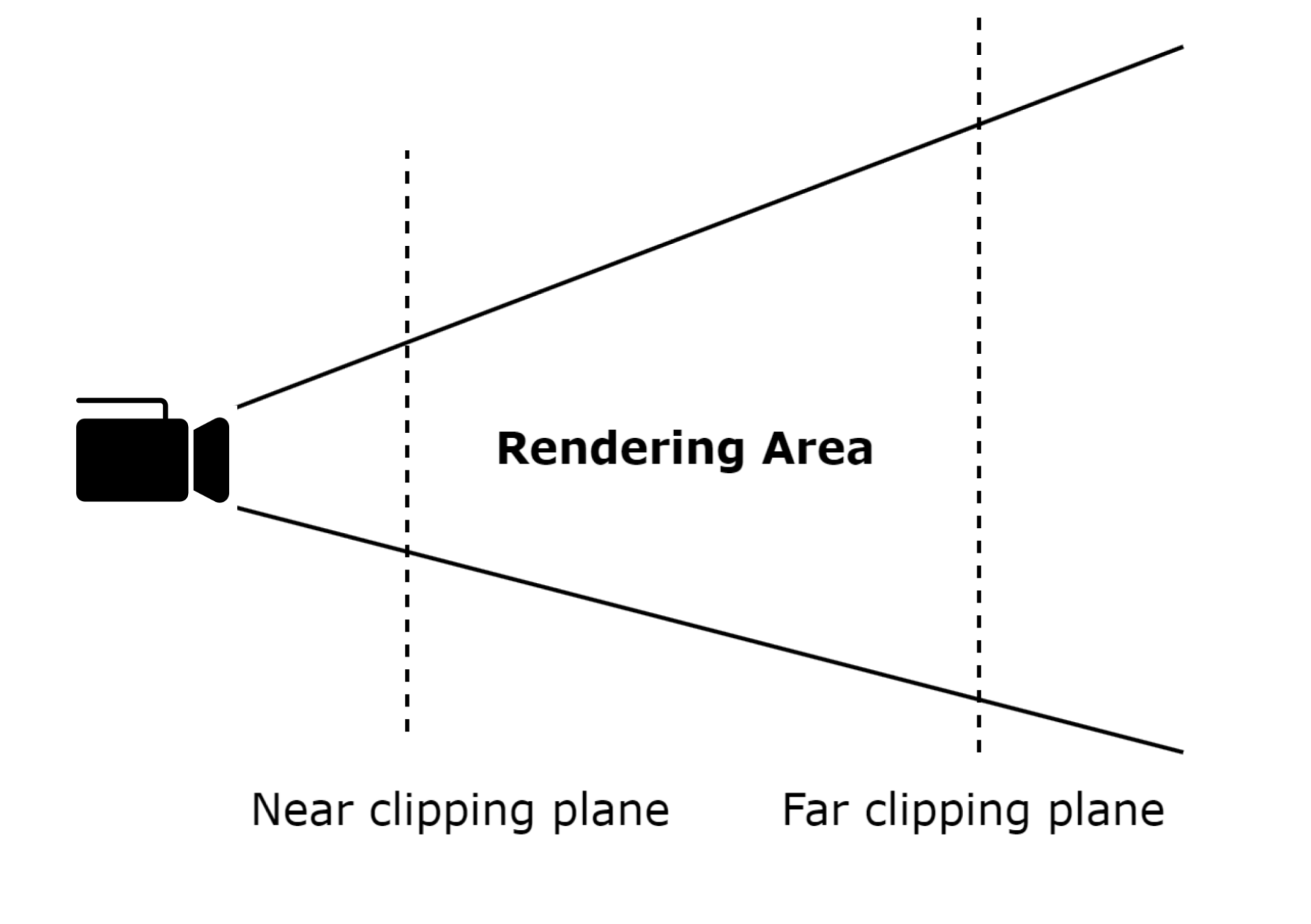
Figure 16:Illustration of the Clipping Range. Clipping range optimizes rendering performance and ensures visual accuracy. By setting appropriate clipping planes, rendering artifacts are prevented and the efficiency of the rendering process is enhanced by excluding objects that are too close or too far from the camera.
Using clipping planes to exclude unnecessary data from a scene can help to optimize rendering times, which is particularly useful in gaming and VR applications. Reducing the range between clipping planes can also be used to slice up a scene into visual layers, such as for viewing thin cross-sections of a 3D medical scan, or when animators render the foreground or background in isolation, so that different effects can be applied to them, before they are brought together again later in a composite image.
In OpenUSD cameras default to a near clipping range of 1.0 scene units and a far clipping range of 1000000 scene units. This is normally sufficient for most needs, however, if you are working with small objects and/or moving the camera close to objects, you may notice that the front of the object starts to disappear from the view because it is falling outside of the near clipping plane. In this case, you will need to reduce the value of the near clipping plane sufficiently to allow the close objects to be rendered. The same can be true of very large or distant objects, where you will need to adjust the far clipping plane.
The following snippet will set the values of both near and far clipping planes. Notice that we do not set the near clipping plane to zero, as that can create issues with math for the projection matrix and cause rendering artifacts, so we’ll keep it as a positive value at 0.1:
camera.CreateClippingRangeAttr().Set(Gf.Vec2d(0.1, 10000))
stage.Save()
We have now set up our stage. We’ve populated it with objects, illuminated it with lights, and set up our camera. All that we’ve done so far has been leading up to rendering an image, so let’s explore that next.
5.4 Rendering your Stage
Once we have created and designed our scene, the final step of the journey is rendering. This is the process of generating a 2D image from a 3D scene, taking into account the complex interplay of light, materials, and geometry.
We will not be using code to render an image from our Statue stage. This is because using the render functions in Blender or USD Composer are generally simpler and more efficient than attempting to render using code, as they come with built-in rendering capabilities that are optimized for ease of use and high-quality output. Rendering with code requires a complex set-up, the configuring of a rendering backend, and the handling of various dependencies, including packages such as ‘UsdImaging’ that are not part of ‘usd-core’ (the focus of this book). Blender and USD Composer streamline this process with user-friendly interfaces.
However, for context, it’s good to understand that there are many use-cases that rely on scripting for rendering, such as automating repetitive tasks, processing multiple scenes, or setting up complex parameters for post-processing or custom lighting configurations. Scripting is also useful for generating procedural environments, integrating rendering into production pipelines, or performing remote rendering on servers that have no GUI, known as ‘headless’ rendering. Scripting can offer greater control and efficiency compared to GUI tools, especially for dynamic and large-scale workflows. For example, in a film production pipeline, scripts can automatically render different shots from a scene with variations in lighting and camera angles, queueing them for batch processing on a render farm—saving time and ensuring consistency across the final output.
To create a final image from your Statue scene, we’ll stick with rendering from the GUI and provide instructions for the built-in rendering tools of Blender and USD Composer.
- Blender offers an excellent rendering engine, Cycles, capable of producing realistic renders of your scene by using ray tracing. It also has a faster, more lightweight renderer, EEVEE, which performs well with basic materials and may be suitable if your hardware is making Cycles too slow for your needs.
- USD Composer offers the RTX Realtime renderer, a very fast, GPU-accelerated renderer ideal for quick previews and representing basic materials. In addition, it has the RTX Interactive which is required for some more complex materials and achieves a greater degree of realism by using ray tracing, at the cost of some speed.
In this section, we’ll introduce you to the basic process of rendering with both Blender and NVIDIA Omniverse, with a set of step by step instructions on the settings to choose before finally hitting the render button.
5.4.1 Rendering in Blender
Firstly, it’s important to realize that the rendering we are about to illustrate refers to the output of a 2D image from the 3D scene in a format such as .png (or .mp4 when doing animation). The 3D GUI is also ‘rendering’ the stage in the viewport continually, in real-time, enabling the user to view a good approximation of what a final rendered output will look like, and the two uses of the term ‘rendering’ should not be confused. We are about to take you through the process of creating a final rendered output, from the viewpoint of our camera on the stage.
Before importing the Statue.usd into Blender, make sure you have completed the steps in the last section to make four of the lights invisible. If this step is skipped, rendering the scene with all six lights active will result in excessive brightness (over exposure). Note that when importing .usd files into Blender, the default setting “Visible Primitives Only” ensures that the four invisible lights will not appear in the final render stage.
When you import the Statue.usd into Blender, the active camera will default to the first on the list. This means that the renderer will use the view from that camera to produce the output image. If you wish to change the active camera, you do so by selecting the camera you intend to use for rendering, then in the 3D viewport opening the ‘View’ drop down menu, selecting ‘Cameras’, and clicking on ‘Set Active Object as Camera’. (See Figure 17) Now the renderer will use the view from the camera that you have activated.
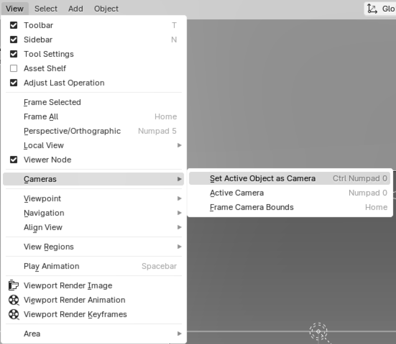
Figure 17:How to set the active camera in Blender if the default camera is different from the one you intend to render from. First select the camera you want to use, then the menu shown here.
Next you will want to select the renderer that you wish to use. If you can use Cycles, you will probably get more realistic results, however, if your hardware struggles with this, use the EEVEE rendering engine. You can select your renderer by going looking in the Properties window and opening the Render Properties tab. (See Figure 18) There you have a drop down menu called Render Engine, which will give you the option of Cycles or EEVEE. If you select Cycles, you will also see another drop down menu called ‘Device’. From this menu select GPU Compute, which will take full advantage of the processing power of your GPU and therefore, be much faster at rendering than the ‘CPU compute’ option.
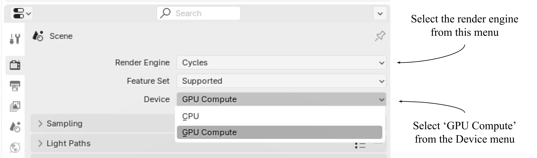
Figure 18:How to set the active renderer in Blender’s ‘Render Properties’ tab. If you choose Cycles, you should also set the ‘Device’ to ‘GPU Compute’
All other settings in the Render Properties tab can be left as default. However, if you are struggling with long render times, we recommend doing some research on the many ways to improve render times in Blender by altering these defaults. A discussion of this subject is beyond the scope of this book, but there are ample sources for more information.
Other important settings include the resolution, aspect ratio and the output location of your rendered image. These are set in Blender’s Output tab, which is also found in the Properties window.
The renderer’s output location will default to “C:\tmp\”, therefore, it is preferable to set the output to a more appropriate path. This is done in Blender’s ‘Output’ tab, which is also found in the ‘Properties’ window (See Figure 19). Under the ‘Format’ dropdown, the resolution variables can be used to control the amount of pixelation and the aspect ratio of your image. Under the ‘Output’ dropdown, you can select your output path by typing it into the field, or clicking on the folder icon to the right of the field and browsing to your chosen folder.
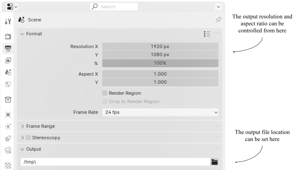
Figure 19:How to set the resolution, aspect ratio, and output location for your rendered image in Blender.
Finally, you’re ready to hit the render button. Find the drop down menu under the Render tab in the general tool bar. From there, select Render image (See Figure 20). This will open a new window called ‘Blender Render’, where you can see your image being rendered.
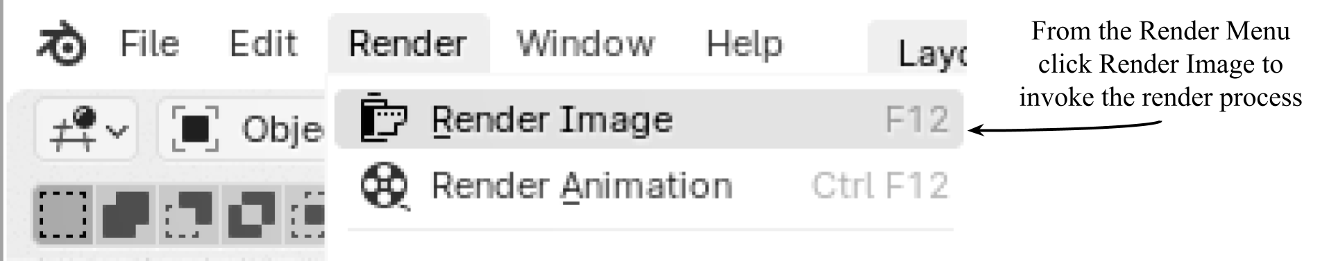
Figure 20:How to initiate the rendering process from the toolbar in Blender.
You may also want to save your image with an alternate name, so that Blender won’t overwrite it with any subsequent renders you make from this scene. To do so, in the Blender Render window, open the dropdown menu under the ‘Image’ tab and select ‘Save As…’. (See Figure 21)
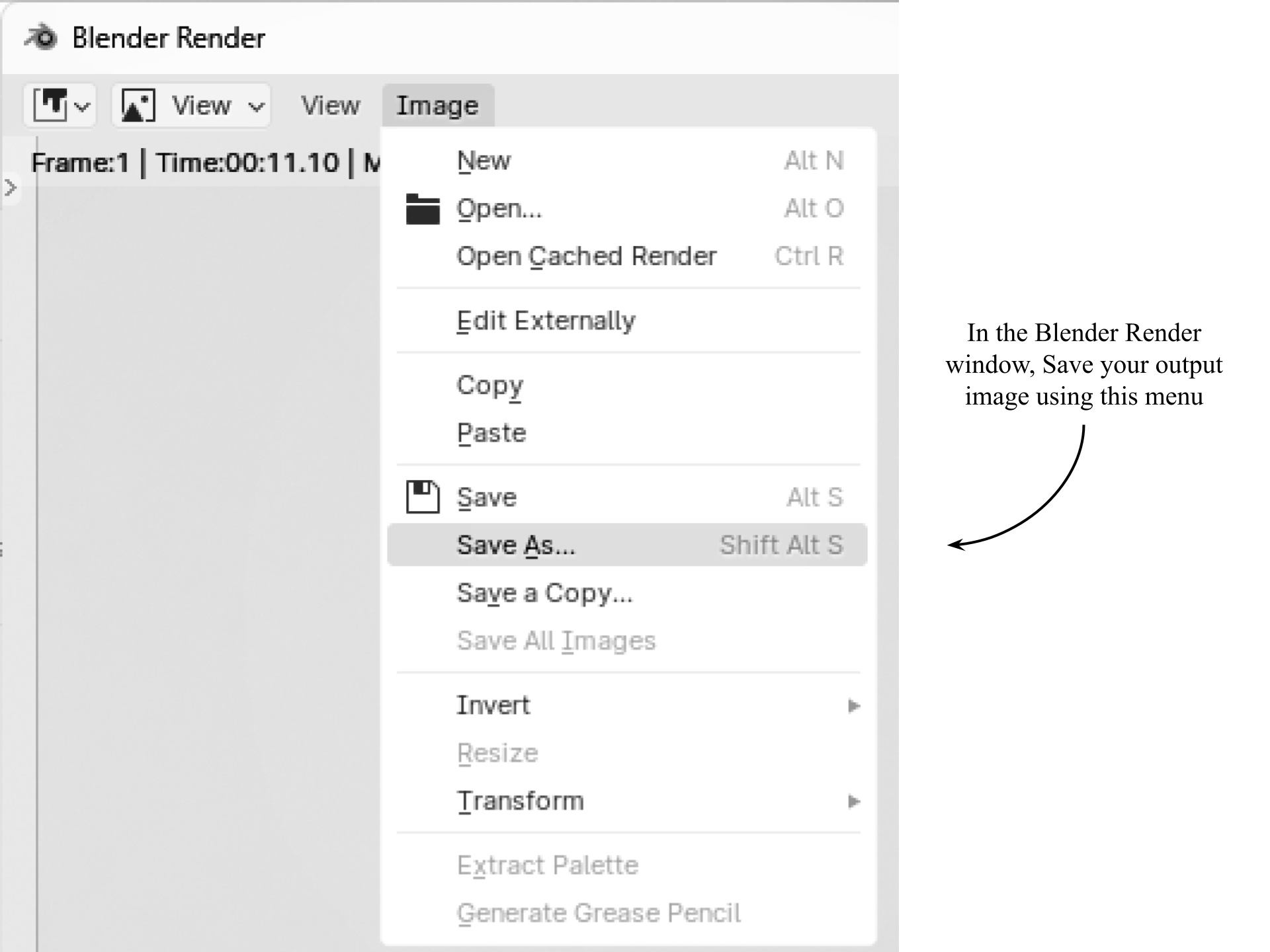
Figure 21:How to save your image from the Blender Render window, thus protecting it from being overwritten by subsequent renders.
Figure 22, shows the render you should now have from the Statue stage, if you used Camera 1 as your active camera, and Cycles as your renderer.
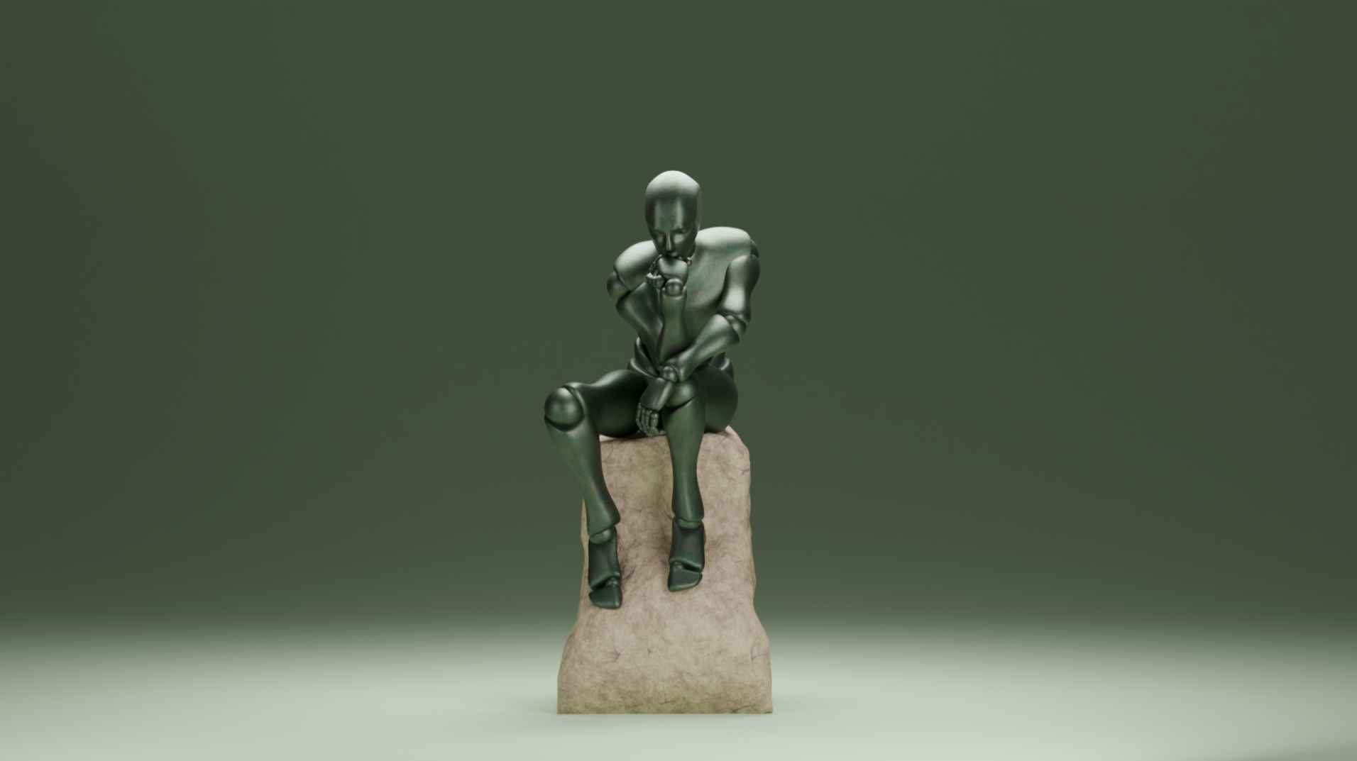
Figure 22:The Statue imported and rendered in Blender using the view from Camera 1 and the Cycles renderer.
5.4.2 Rendering in USD Composer
If you have an NVIDIA RTX GPU, you will likely be using USD Composer’s rendering capabilities. The steps to create a rendered image are similar to Blender, though there are some slightly different menus to navigate.
In USD Composer, all of the following steps can be carried out from one window, the ‘Movie Capture’ window. Despite its name, this is also used for capturing still images. Figure 23 shows how to access the Movie Capture window from the drop down menu under the ‘Window’ tab in the toolbar.
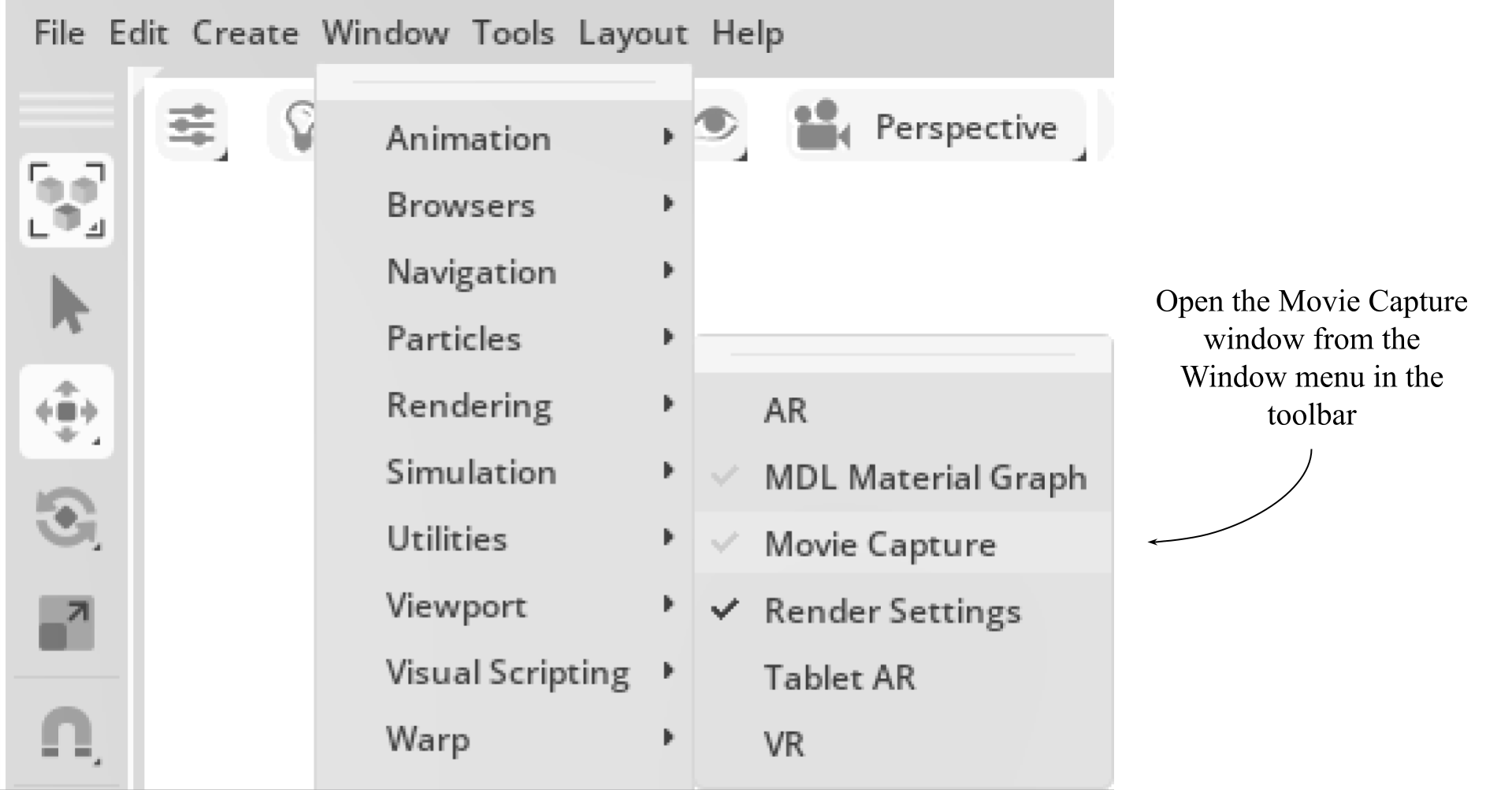
Figure 23:How to open the Movie Capture window in USD Composer.
Within the Movie Capture window, you can now set all the parameters for your render, and invoke the render process. Figure 24 shows the top section, ‘Capture Settings’, of the Movie Capture window that allows you to choose the active camera and the resolution. The active camera will default to the one you are currently viewing the stage through. The resolution may be changed to alter the level of pixelation in your render and/or change the aspect ratio of the output.
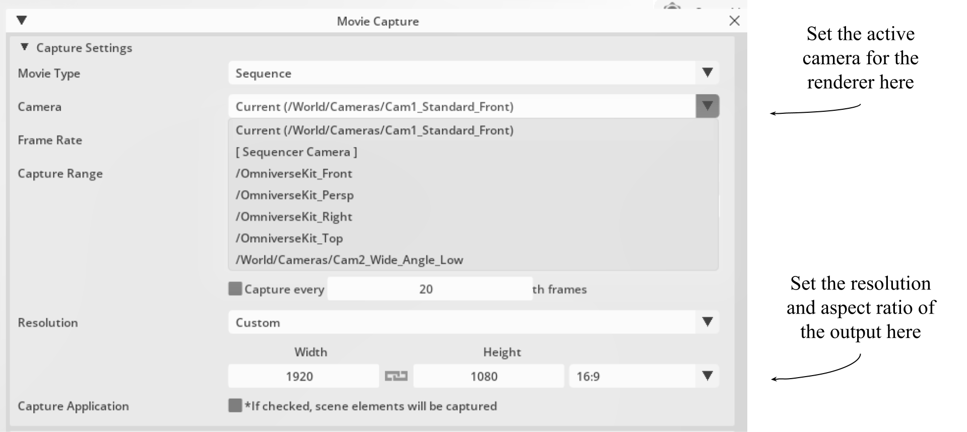
Figure 24:How to adjust the active camera and resolution of your output in the Movie Capture window of USD Composer.
In the middle section of the Movie Capture window is the ‘Rendering’ menu. Figure 25 shows the drop down menu that allows you to select the actual render engine that you want to use. It will default to the renderer you are currently using in the viewport.
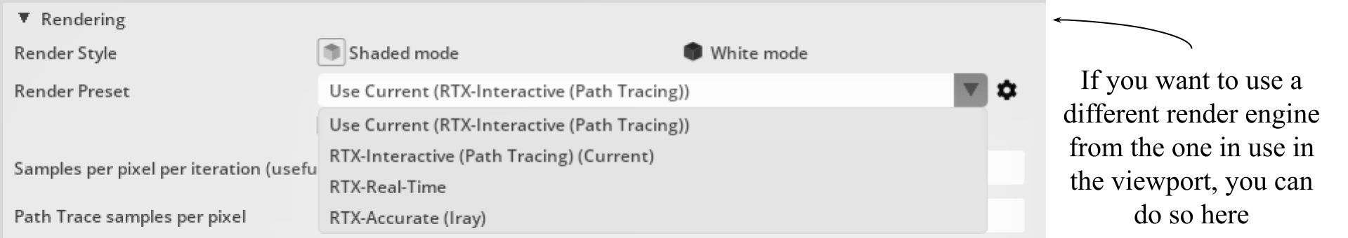
Figure 25:How to change the render engine that will carry out the render process in the Movie Capture Window of USD Composer.
Finally, shown in Figure 26, the lower section of the Movie Capture window, the ‘Output’ section, gives access to the output path setting, the naming and numbering of the image and the all important button to invoke the render process. In this case, we only want to capture a still image, so we’ll use the ‘Capture Current Frame’ button.
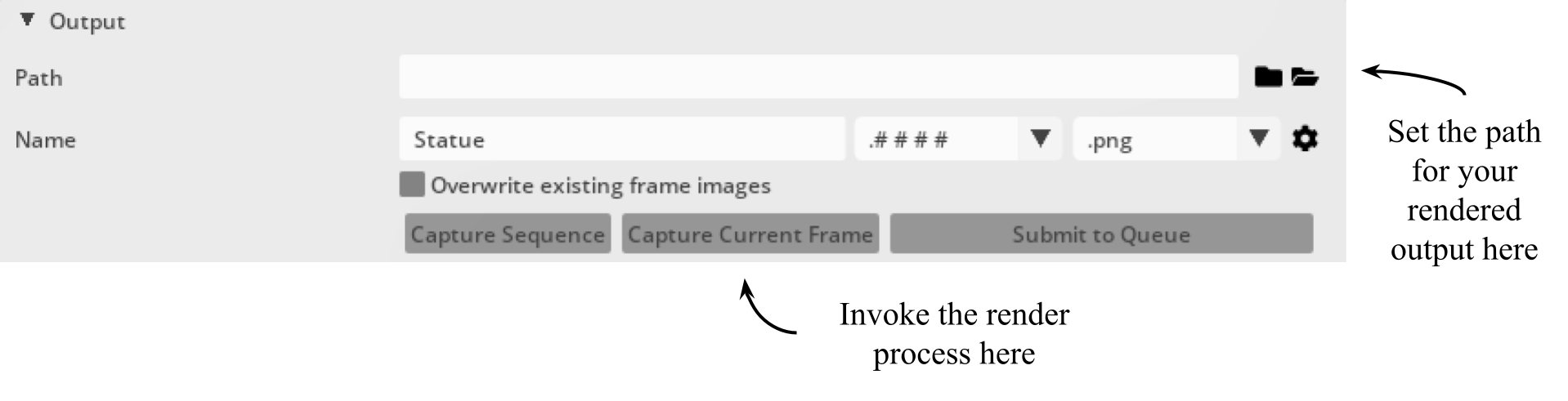
Figure 26:How to select the output file path, name your render and invoke the render process in USD Composer.
Once the Capture button is clicked, a new window will open showing the progress of the render. You can then navigate to your chosen output folder and view your fresh, new render. Figure 27 shows the output render from USD Composer using the RTX Interactive renderer. When compared to the output from Blender shown in Figure 22, you will notice the similarity, highlighting the ability of the USD format to provide consistency across platforms and renderers.

Figure 27:The Statue rendered in USD Composer with Camera 1 as the active camera and the renderer set to RTX Interactive.
We hope this introduction helps you in rendering OpenUSD scenes. We have highlighted the importance of careful planning and consideration of both lighting and cameras before rendering and introduced two excellent tools that can be used to bring these scenes to life with high quality renders. Much of the process of lighting and camera positioning is subjective and part of the whole creative process, so feel free to modify any of the choices we’ve made above to fit your specific needs!
Summary
- Carefully chosen lighting techniques are essential for creating a realistic and professional look, as they can add depth, atmosphere, and make models appear more three dimensional and lifelike on the stage.
- Types of lights covered include cylinder, disk, rectangle, sphere, distant, and dome lights. Each type serves specific purposes and can be configured programmatically to achieve desired lighting effects.
- The three-point lighting system (key, fill, and back light) is a quick and simple setup that will work for many situations. It provides broad illumination of a subject, separates it from the background, and avoids creating too many deep shadows.
- Understanding and configuring camera angles and settings, such as focal length, fStop, and focus distance, is essential for achieving the desired visual output. The choice of viewpoint and camera settings can dramatically alter the viewer’s perception of the scene, making them feel immersed within it, drawing their attention to key elements, or playing with their sense of perspective.
- Rendering the scene can be done by different 3D software tools to apply rendering properties and settings, producing high-quality visual outputs.